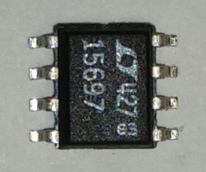
I am trying to figure out the Pin: 1 location on the Digital Filter IC: LTC1569-7 for a System Blue build. There is no point at one corner of the housing. See image below. Could someone help identify the Pin: 1 location. Thank you and appreciate it.
(2016-06-18, 13:00)rwhalb@verizon.net Wrote: I am trying to figure out the Pin: 1 location on the Digital Filter IC: LTC1569-7 for a System Blue build. There is no point at one corner of the housing. See image below. Could someone help identify the Pin: 1 location. Thank you and appreciate it.
By the datasheet, it should have a wedge along one side - that side is pins 1-4 (counter-clockwise), the other side is 5-8.
(2016-06-18, 13:00)rwhalb@verizon.net Wrote: I am trying to figure out the Pin: 1 location on the Digital Filter IC: LTC1569-7 for a System Blue build. There is no point at one corner of the housing. See image below. Could someone help identify the Pin: 1 location. Thank you and appreciate it.
By the datasheet, it should have a wedge along one side - that side is pins 1-4 (counter-clockwise), the other side is 5-8.
So from the image above would you agree that wedge is on the left side and Pin: 1 is in the upper left-hand corner?
(2016-06-18, 13:00)rwhalb@verizon.net Wrote: I am trying to figure out the Pin: 1 location on the Digital Filter IC: LTC1569-7 for a System Blue build. There is no point at one corner of the housing. See image below. Could someone help identify the Pin: 1 location. Thank you and appreciate it.
By the datasheet, it should have a wedge along one side - that side is pins 1-4 (counter-clockwise), the other side is 5-8.
So from the image above would you agree that wedge is on the left side and Pin: 1 is in the upper left-hand corner?
Pardon me for butting in, but reading about BLUE construction I'm interested.
Is this photo taken from the bottom of the chip with the little pins projecting up towards the viewer, or is the perspective such that the feet ar actually down towards the surface it is resting on?
For some reason as I look at the chip it looks like it was placed flat surface down with the legs up towards the camera.
That would make a heck of a difference, too.
Just asking before you solder expensive stuff to a hard to remove spot.
(2016-06-18, 15:23)Dale.Reid Wrote: Pardon me for butting in, but reading about BLUE construction I'm interested.
Is this photo taken from the bottom of the chip with the little pins projecting up towards the viewer, or is the perspective such that the feet ar actually down towards the surface it is resting on?
For some reason as I look at the chip it looks like it was placed flat surface down with the legs up towards the camera.
That would make a heck of a difference, too.
Just asking before you solder expensive stuff to a hard to remove spot.
Dale
Dale:
Thanks for your interest. The photo is taken from the top of the chip. I used by Samsung Galaxy S5 using a magnifier app. The legs are down away from the camera.
Do you agree then that Pin: 1 is in the upper left-hand corner?
All true. The "chamfer" edge is the 1-4 pin side. It is on the datasheet for the part at http://cds.linear.com/docs/en/datasheet/15697fs.pdf. The first page has the pin diagram where the gray area is the pin 1-4 side. There is also a drawing near the end of the datasheet.
The manufacturer's datasheets are the best source for information on a part. Most are available free if you know where to find them.
99% of the time, the laser etched markings are on the top side of the part.
but how do i know, that i should solder the digital filters on the board or not.
is it depending of the noise-level? but how do i measure it? and what is the max level of it?
2016-07-19, 12:32 (This post was last modified: 2016-07-19, 12:33 by DelandeC.)
Hello Patrick,
The digital filters option is mainly used to cut the signal above a certain frequency which disturbs a lot the detector.
This can be very usefull to get rid of LF emitters such a military radio or so.
Without your station up and running this is difficult to give you a better diagnosis.
Note that the noise can be reduced by grounding the controller to i.e. a cold water pipe and by using a clean and "silent" power supply.